
In the previous example, you worked with the card object. Nuke also includes primitive geometry, which can be used as set-extension geometry or placeholders for other elements you plan to add to scene.
| 1. | In the “3Dinteg_tutor.nk” project file, locate the node tree labeled “Working with Geometry.” |
We’ve already supplied the 3D node tree with a camera for you, so you need to add the geometry objects, and also create a “scene” where they can co-exist.
| 2. | Right-click over the Node Graph and choose 3D > Scene. Connect Scene2 to ScanlineRenderG. |
| 3. | Connect a Viewer to the ScanlineRenderG node and switch to the 3D perspective view. |
| 4. | Right-click and choose 3D > Geometry > Cube. |
The default cube primitive appears at the center of the 3D workspace. Let’s reduce the number of subdivisions on the cube.

| 5. | In the Cube1 control panel, change the rows parameter to 4. Change the columns parameter to 4, also. |

| 6. | Connect the Cube1 node to the Scene2 node. Now let’s adjust the shape of the cube. |

| 7. | Reduce the height of the cube by dragging the top-center point down. |

| 8. | From the view dropdown menu, choose the front view to see a non-perspective view of the cube. These non-perspective views can help you size and position objects with more accuracy than you might get in a perspective view. |
Mm... the cube is actually below the x-axis. Let’s move it up, but check the values in the Cube1 control panel.
| 9. | Drag the top of the cube until the t (top) value in the Cube1 control panel is about 0.3. Drag the bottom of the cube to align it with the x-axis. |

| 10. | It looks like you don’t need 4 divisions on the sides of the cube, so change the number of rows to 2 in the Cube1 control panel. |

Now let’s add a few more primitives - a cylinder and a sphere.
| 11. | Right-click on the Node Graph and choose 3D > Geometry > Cylinder. Connect the Cylinder1 node to the Scene2 node. |

| 12. | Change the view to 3D (V) and zoom out a little to see the whole cylinder. |

| 13. | In the Cylinder1 control panel, set the rows to 1, the columns to 20. |

| 14. | Set the radius to 0.35 and the height to 1.5. Also check the box for close top. |
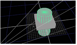
So now you have a cylinder in the scene.
| 15. | Choose front from the view dropdown menu and move the cylinder up to rest on top of the cube. |

| 16. | Now add a sphere. Choose 3D > Geometry > Sphere. In the Sphere1 control panel, set both the rows and columns to 15, and change the radius to 0.35. |

| 17. | Make sure the Sphere control panel is open and move the sphere object to cap the top of the cylinder. |

| 18. | Select the 3D from the view dropdown menu and rotate the view around the objects in your scene. |
At this point, they have no surface properties, so you’ll need to connect a 2D image from the Node Graph to each object.
| 19. | In the Node Graph, connect the concrete.jpg to each of the objects. |

