added to the scene.
It cannot be textured using
the original footage.
textured separately.
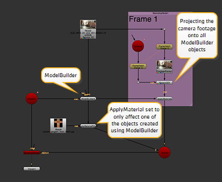
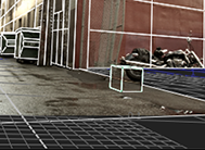
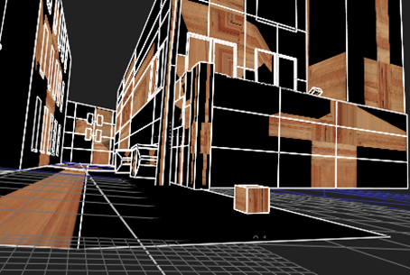
If you've used ModelBuilder to add new objects over the top of your 2D footage (for example, added a new window to a building or extra bins alongside a street), you can't project your 2D footage over those objects because they were never in the original footage. Instead, you need to supply a texture from somewhere else and map it over the surface of your 3D object.
|
|
|
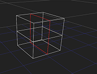
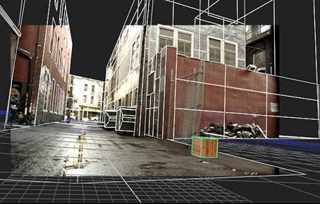
| An extra cube has been added to the scene. It cannot be textured using the original footage. |
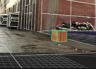
Here, the cube has been textured separately. |
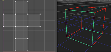
To map a texture image over the surface of your 3D object, you first need to flatten your 3D object out into 2D space through a process called UV unwrapping. This generates UV coordinates for each vertex in the object, allowing you to map points on the surface of your 3D object to pixels in your texture image.
|
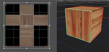
| A 3D cube flattened out into 2D space. |
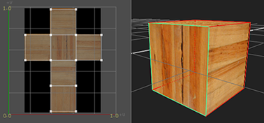
|
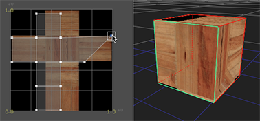
| Previewing a texture image while editing the cube's UV coordinates. |
TIP: UVs are simply 2D coordinates that tell 3D applications how to apply a texture to a model. The letters U and V were chosen because X, Y, and Z were already used to denote the axes of objects in 3D space. The U coordinate represents the horizontal axis of the 2D texture, and the V coordinate the vertical axis.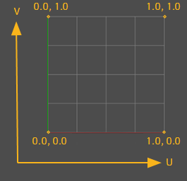
The process of UV unwrapping is roughly the following:
| 1. | Define where to cut the model in order to flatten it out into 2D space. See Creating Seams on Your Model. |
| 2. | Unwrap the model and preview the results. See Unwrapping Your Model and Previewing Its UVs. |
| 3. | Edit the generated UVs as necessary. See Editing UVs. |
| 4. | Apply a texture to your model. See Applying Textures. |
To prepare your model for UV unwrapping, you need to mark some seams. The seams tell ModelBuilder where it's allowed to cut the model in order to flatten it out into 2D space.
TIP: If you don't have enough seams marked, the unwrapping will be very poor with lots of overlapping faces as well as stretching and distortion. On the other hand, too many seams can make it difficult to texture the object, as the gaps in the seams can easily become noticeable on the textured object. If possible, it's a good idea to hide seams in areas where they will not be seen.
| 1. | If you have created several objects using the same ModelBuilder node, click |
| 2. | In the ModelBuilder toolbar, click |
| 3. | Repeat one or more of the following until you've got a good set of seams: |
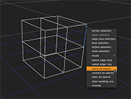
• To mark an edge as a seam, right-click on the Viewer and choose edge selection. Select an edge on your model, right-click, and choose mark as seam.
|

|
• To mark an edge loop as a seam, right-click on the Viewer and choose edge loop selection. Select an edge loop on your model, right-click, and choose mark as seam.
|
|
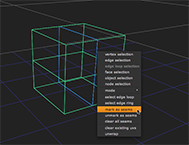
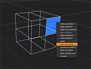
• To mark all edges around a face as seams, right-click on the Viewer and choose face selection. Select a face on your model, right-click, and choose mark as seam.
|
|
TIP: You can also select a face loop and mark all edges around it as seams. To do so, select at least two faces on your model, right-click, and choose select face loop. Then, right-click on the Viewer again and choose mark as seams.
• To remove an edge, edge loop, or face from the set of seams, select it in the Viewer, right-click, and choose unmark as seam.
• To clear all seams, right-click on the object and choose clear all seams.
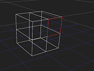
Any edges that have been marked as seams are displayed in red in the Viewer.
| 4. | Proceed to Unwrapping Your Model and Previewing Its UVs below. |
TIP: The easiest way to create a good set of seams for buildings (or any other roughly cubic or cylindrical object) is to 1) select the top faces and mark them as seams, 2) select the bottom faces and mark them as seams, and 3) select edges along the side of the model that connect the top to the bottom and mark them as seams.
Once you're happy with your set of seams, you are ready to unwrap the model.
| 1. | Right-click on the Viewer and choose object selection. |
| 2. | Right-click on your model and choose unwrap. |
A colored border appears around the Viewer window to indicate that the action is in progress.
| 3. | Press Return to complete the unwrap. |
ModelBuilder generates UV values for each of the vertices on your model. The unwrapped model appears in the UV preview window in the top left of the Viewer.
| 4. | To display a 2D texture image as a background in the UV preview window, connect the image to ModelBuilder's tex input and make sure the Preview dropdown in the ModelBuilder properties (or on top of the Viewer) is set to tex input. To also see the tex input on the model in the 3D Viewer, set display to either textured or textured+wireframe in the ModelBuilder properties. |
| 5. | To zoom in or out of the UV preview window, press Ctrl/Cmd+Alt and drag. |
| 6. | To pan the UV preview window, press Ctrl/Cmd and drag. |
| 7. | To change the size of the UV preview window, click and drag on its lower right corner. |
| 8. | To hide the UV preview window, disable uv window at the top of the Viewer. |
| 9. | Proceed to Editing UVs below. |
TIP: If you are not happy with the generated UVs, you can right-click on your model and select clear existing uvs. If necessary, you can also change the seams and unwrap your model again. Each time you do, ModelBuilder replaces the UVs you had with the newly generated UVs.
You can tweak the controls at the top of the Viewer or edit the UVs manually in the UV preview window.
| 1. | Adjust the following controls at the top of the Viewer: |
• iterations - The number of times the unwrapper applies its rules about how to move the UV coordinates towards good locations. This gives you a speed vs. quality trade-off: more iterations give a better result but take longer to unwrap. Note that the results can only be improved up to a point, and where that point is depends on the complexity of your model.
• threshold - The unwrapper stops before reaching the maximum number of iterations if it sees that the improvement from iteration to iteration is negligible. The threshold control tells it how much change is considered negligible. If the amount of change between iterations is below the threshold, the unwrapper stops. This is another way to trade off quality for speed. You generally use this if you want a higher quality result: if you've increased iterations but the unwrapper is stopping before reaching the maximum, you can lower the threshold to make it keep running.
• separation - The number of pixels to leave between each patch in the unwrapping. If you don't have enough pixels between your patches, you can get color bleeding through from neighboring patches when you use the texture. A higher value means more widely spaced patches, but also more wasted space in your texture image.
As you edit these controls, the UV preview window updates to allow you to see the effect of your changes.
| 2. | If necessary, you can also edit the UVs manually in the UV preview window: |
• To edit a single vertex, drag it to a new location.
• To edit several vertices together, select them and use the transform jack that appears to translate, rotate, or scale the selection. The transform jack is the same one used elsewhere in Nuke, so all the controls work the same way. For example, you can click and drag on the handles to scale out from the center, or Ctrl/Cmd+click and drag to scale out from the opposite edge.
| 3. | Proceed to Applying Textures. |
At this point, it may be that you've got several objects in the scene that you still want to project your camera footage onto (see Projecting Textures onto Your Shapes), but there's one object that you want to texture differently. There are two ways to do this:
• You can export your model as a separate geometry node and use an ApplyMaterial node to texture it. This can be a convenient way to work if your geometry is finished and locked off, so you never need to go back and change it. But what you lose with this is the "live" view: if you do need to go back and edit the object, you have to export it again. See Method 1.
• Alternatively, you can add an ApplyMaterial node directly after your ModelBuilder node and tell ApplyMaterial to ignore all the geometry that doesn't match the filter you give it. See Method 2.
| 1. | In the ModelBuilder properties, select the object that you want to texture differently. |
| 2. | At the bottom of the properties panel, set the bake menu to Selected geometry and click Bake. |
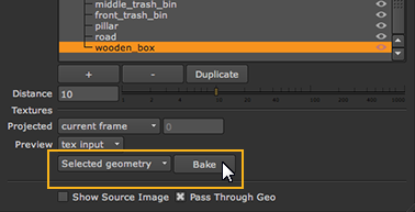
ModelBuilder creates a geometry node for the selected object.
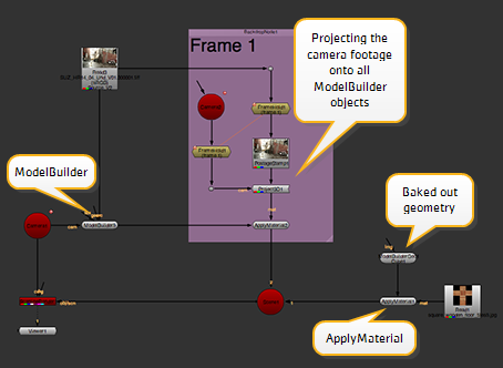
| 3. | From the toolbar, select 3D > Shader > ApplyMaterial to create an ApplyMaterial node. |
| 4. | Connect the geometry node you created in step 2 to the unnamed input of the ApplyMaterial node. |
| 5. | Then, connect your 2D texture image to the mat input of the ApplyMaterial node. |
The ApplyMaterial node applies the texture from the mat input onto your 3D geometry object. (To be able to see this in the 3D Viewer, you may have to hide the object in the ModelBuilder properties.)
| 6. | Connect the ApplyMaterial node to your Scene node and use a ScanlineRender node to render all the objects connected to that scene. |
| 1. | From the toolbar, select 3D > Shader > ApplyMaterial to create an ApplyMaterial node. |
| 2. | Connect the unnamed input of the ApplyMaterial node to your ModelBuilder node and the mat input to your 2D texture image. |
By default, ApplyMaterial applies the texture from the mat input onto all objects in your ModelBuilder node.
| 3. | To only apply the texture onto a particular object, open the ApplyMaterial properties and set filter to name. This allows you to tell ApplyMaterial to ignore any geometry that doesn't match the filter. |
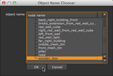
| 4. | To set the filter, click the choose button. In the dialog that opens, select the object you want to apply the texture to and click OK. |
TIP: You can also Ctrl/Cmd+click or Shift+click to select multiple objects.
For more information on ApplyMaterial, see Applying a Material Using the ApplyMaterial Node.
| 5. | Connect the ApplyMaterial node to your Scene node and use a ScanlineRender node to render all the objects connected to that scene. |